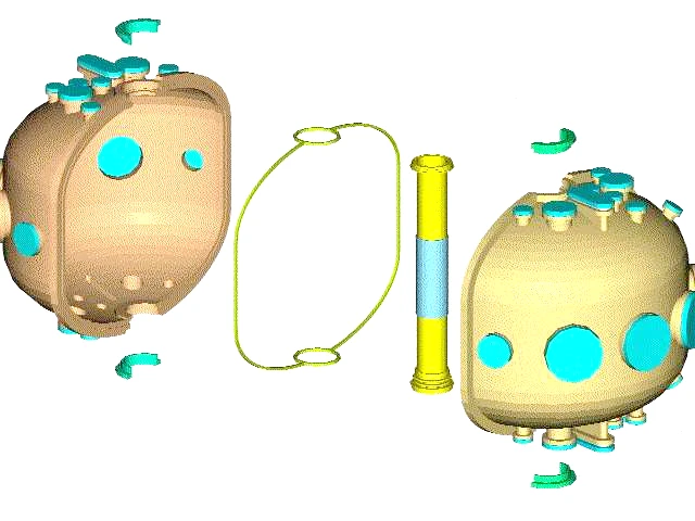
The key parameters of SUNIST are: major radius , minor radius , aspect ratio , elongation , on-axis toroidal field , plasma current , and total flux consumption . To conserve the extremely limited available flux, SUNIST incorporated highly unconventional solutions from the outset. As shown in Fig. 3, the vacuum vessel was split by an insulating gap instead of forming a contiguous conducting shell. This resulted in a combined modular structure consisting of two insulating hemispheres and a center column. Consequently, the vessel sealing utilized a T-shaped Viton gasket. Despite concerns about vacuum compatibility, this novel sealing approach proved quite effective over two decades of operation. From 2002 to 2008 before refurbishment, minor leaks were observed near the top T-joint. However, after repairs and gasket replacement during the 2008 upgrade, no issues have recurred since. The measured leak rate is below , enabling maintenance of a base pressure that satisfies discharge requirements, with a turbopump. While defying conventions, this insulating vacuum vessel design significantly reduced eddy currents. Together with the thin cylindrical wall of the SUNIST center-post, the total eddy effect was minimized. This facilitated easy gas breakdown, and was a key factor enabling prompt plasma initiation during first plasma operations on November 4, 2002.
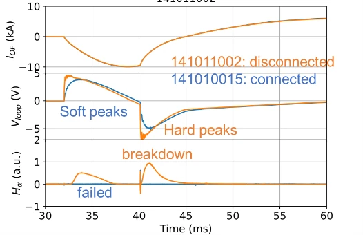
We conducted dedicated experiments to investigate the impact of the insulating gap on eddy currents. By electrically shorting or leaving open the gap with removable blocks, quantitative comparisons were made on key discharge parameters with and without the gap. As shown in Fig. 4, the overall volt-second saving was moderate at ~10%. However, the peak loop voltage reached above 7 V with an insulating gap, forming a sharp spike that enabled easy breakdown. In contrast, with a fully conducting wall, the loop voltage remained below 5 V with a smooth envelope, failing to breakdown the gas. This demonstrates the clear benefit of the insulating slit for reliable discharge initiation.
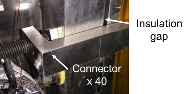
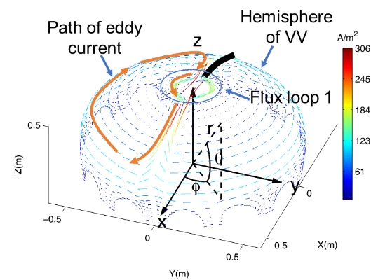
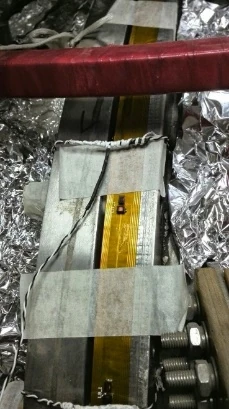
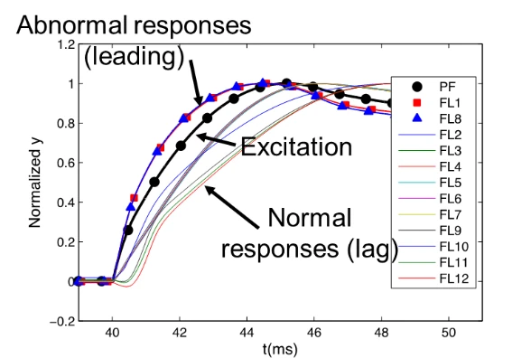
Nonetheless, the gap did not eliminate eddy currents entirely, but resulted in a unique 3D distribution. The broken path along the wall surface formed eddy current loops Hemispherically, causing reversed flow directions between the equator and top/bottom (Fig. 5 left). At the equator, conventional retarding eddy currents opposing excitations’ growth were observed. But eddy currents at the top and bottom exhibited an anomalous advanced phase, even preceding the excitation waveform, which complicated equilibrium analysis (Fig. 5 right). To resolve this 3D eddy challenge for equilibrium reconstructions, an extensive array of wall probes was installed, directly revealing the measured polarity reversal along the vertical axis (Fig. 5 center), confirming suspicions[2].
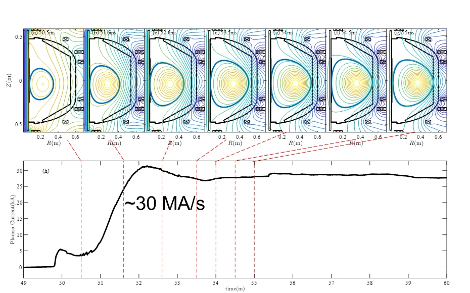
Moreover, a response-function[3] based eddy current analysis procedure was developed. By isolating and subtracting the eddy component from raw signals, this technique recovered the true plasma and/or magnetic field response. Integrated with our equilibrium code SU-EFIT, it significantly improved reconstruction accuracy, enabling the identification of up-down asymmetric shapes. Despite ramp rates up to 30 MA/s and strong eddy effects in early current rise, quality equilibrium analyses were achieved using this comprehensive approach (Fig. 6).